It’s been a hot minute, hasn’t it.
Since our AI overlords started exercising their self-granted right to non-consensually devour the Internet for their own theoretical future monetary gains, I haven’t really felt like sharing content on the web.
I will say this: If you would like to know how to open up the Arturia Keylab 61 Mk II and mess around with the pitch wheel – specifically inverting the polarity – then feel free to get in touch.
Well, it’s been a while. Just over a year ago I took a full-time job and it has pretty much consumed all available free time. So musically, things have definitely been on hiatus. However, I have been keeping an eye out for sales and deals and there has been some re-tooling going on here in the Studio. I didn’t acquire or upgrade these all in one go! It’s been 13 months.
Recent software arrivals:
- Arturia Pigments 4
- Modartt Pianoteq 8 Standard (upgrade from Stage)
- Klevgrand Tomofon
- MiMu The Jellyfish
- MeldaProduction Sound Factory
- AAS Chromophone 3
Hardware:
- Line 6 Helix Floor
- True Temperament Telecaster neck
I have no idea at this point which instruments are going to get used in the next project, but I should have some fun figuring that out.
The Circles project is still a thing: I have songs planned out, musical ideas and full lyrics; just nothing committed to disk at this point.
My next project might be something different, though. More to come on that. Let’s just say it involves escaping the “Tyranny of the Grid”.
I also need to sell or donate some equipment.
The Lede: Apple devices are applying Automatic Gain Control (AGC) to my digital audio files, and I don’t know why.
Update: Not that simple. Turns out it is VLC on iOS that is the culprit. See additional notes at the bottom of this post.
Back to the original post: I don’t normally listen to digital music streamed through my iPhone, because a) I won’t go near iTunes, and b) I have a couple of perfectly good USB MP3 players, which I’ve used on cycling outings.
Recently we’ve been ripping our audio CDs to FLAC format and loading them into a NAS from Synology, which provides a DLNA (Universal Plug-n-Play) audio server. It works fine although the available client applications that you can use to listen to the files are just okay. VLC seems pretty good, and it is supported on all our computers (Windows, Linux, Mac) and mobile devices (Android, Apple).
This weekend I did some work in the garden, and because I was within our WiFi zone, I decided to try streaming music from the DLNA server using VLC on my new iPhone, an SE 2020.
It sounded like shit.
Now, Apple did a lot of funky stuff in recent IOS versions (14, 15) involving monitoring playback volumes, and reducing headphone levels if you exceed recommendations. To be clear, I’m not talking about that. That’s a whole other rant. No, I’m talking about Automatic Gain Control, which used to be a thing on tape recorders to limit audio levels hitting the tape, or on playback (sometimes called “dynamic loudness control”).
It was really noticeable on my latest completed project, the Annulus Suite.
Annulus was stitched together in a Cakewalk project and mastered at 14 LUFS in order to retain the dynamics. I thought the end result was pretty good. I exported it to a lossless, compressed format called FLAC using CD-quality 16 bit audio depth. The results were pretty good, and that ‘s the version I uploaded to BandCamp to make available for purchase – the official release, if you like.
So it was very distressing to hear the peaks squashed, and any significant bass pulling the levels down, the dynamics chewed away and spat out. It was being pushed through an audio compressor.
I couldn’t find any obvious documentation about this from Apple (apart from the aforementioned digression about the nanny-state excessive headphone volume control). Where was this effect coming from? Was it the Apple Earbuds? VLC? The iPhone? I did some comparisons, and here are the results:
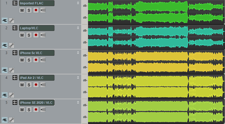
The FLAC file is located on the Synology NAS, available to stream via DLNA. I used VLC to play the audio file, and recorded the output from various mobile devices via the 3.5mm audio jack, into my ECHO Layla 3G PCI audio interface.
- Track 1 is the FLAC file, directly imported into the project.
- Track 2 is from my Windows 10 laptop running VLC;
- Track 3 is from my iPhone 5c (IOS 9.3.5) running VLC app;
- Track 4 is from my iPad Air 2 (IOS 13.6.1) running VLC app;
- Track 5 is from my iPhone SE 2020 (IOS 15.0.2) running VLC.
Because each device had slightly different levels on the volume control, I normalized each clip for comparison purposes. The Windows playback sounds great and seems unchanged. However I hope it is obvious to you that the Apple devices are severely messing with the dynamic range on playback. I don’t think there is any practical difference between tracks 4 and 5, but it is interesting that the iPhone 5c running the older OS is still clearly affecting the output dynamics, albeit not as badly as the later devices.
I’m going to publish this post now, but I’m not done researching. More as it comes to hand.
Update: A couple of further tests today. Stick to one device, but compare apps. I used VLC, Synology’s DS Audio, and FlacBox:
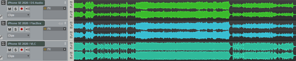
Each track was recorded from the iPhone SE using the same volume level on the iPhone control (one notch below 100%). Again, I’ve normalized the clips for display comparison.
DS Audio and FlacBox do not apply any AGC to the output. It sounds dynamic and great. So… is it just VLC? VLC has always been my “gold standard” on conventional desktops (Linux, Windows) so it is distressing to find that the mobile version appears to be misbehaving.
Additional Update: This thread on Reddit may have the answer: Does iOS VLC app put a volume maximizer on all audio by default?
There ARE EQ controlls in the iOS app! You have to be in Landscape mode… And guess what? The “Preamp” is above 0db by default and seems to be causing the ducking effect! I lowered the preamp to 0 and my issue is resolved! I’d like to say this is a bug; by default VLC should not be doing any DSP.
plutoniumhead, reddit.com/r/VLC
I carefully set the EQ to “Flat” and adjusted the preamp to 0db. The result:
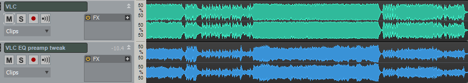
Okay, it worked. There’s much less compression or ducking going on. I won’t say “none” because I can’t tell without extra careful comparison which I can’t be bothered doing. These controls are hard to find; tricky to adjust; and not persistent between songs! This is not a solution; barely even a work-around.
Also, this thread on the Videolan forum shows that there are other folks who have noticed the problem, complained about it, and the “known issue” doesn’t seem to be able to be addressed competently. Yeah, I said it. Even the “fixed in 4.0” comment doesn’t fill me with confidence that the issue has even been identified correctly. This is sad.
Until further notice, I do not recommend using VLC on iOS for audio playback.
I’ve created a page for the Circles album and that’s now available. Currently it only covers “vol.3” because that’s the only selection from it available on BandCamp at this time. I have to get on with writing the next chunk of music!
Vol.2 is next, and most likely will consist of three individual songs rather than a related suite. I’m currently working on the first of these, ensuring that the melody is pitched right for my voice, and that I’m not plagiarizing myself (or indeed, any other artist). At least, not too obviously. This track I’m working on definitely wants to use a chord sequence from “Paradigm Shift” and I’m not sure that I can let it do that so blatantly.
Time for another post in the series on Roland A-80 MIDI Keyboard Controller servicing. Previously:
- The Roland A-80 arrives
- Changing R43 to make the aftertouch more responsive
- Replacing the key bed “upper” felt
- Replacing the D4 key’s rubber dome switch
- Replacing the LCD display
The short:
- Use Velostat to replace the pressure-sensitive cells under each key.
- Change R43 to a variable resistor of about 27k and set it mid-way
- Enjoy.
The longer, illustrated version
Despite the R43 fix, the touch response has never really been usable. The mechanism Roland used clearly didn’t remain viable over time. The risk of screwing up the key bed completely has always deterred me from experimenting in this area.
And then, there was this thread on Computer Music Guide forum, “Roland A-80 (Aftertouch Repair)”. Back in 2014, noisevoid had the great idea to experiment with alternative pressure-sensitive rubber to see if they could restore touch-sensitivity to the notoriously unresponsive A-80 key bed. Their research identified a product from Zoflex as a possible solution…. and then they were never heard from again on that thread.
But the idea intrigued me, and after Syntaur alerted me that the “upper” key felt strip was back in stock, I decided it was time to go deeper. I placed an order for a sheet of the Zoflex product… and also did more research on pressure-sensitive materials.
One finding in particular looked very interesting: In 2016 Liam Lacey had implemented a “toy keyboard synthesizer” with pressure sensitivity using a product called “Velostat”. Intrigued, I ordered a sheet as an alternative.
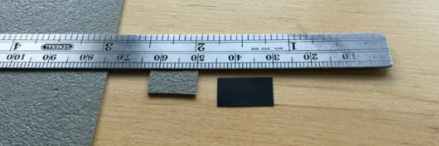
Eventually the samples showed up. The Zoflex rubber sheet was about 1mm thick and quite “spongy” and quite expensive for a 10cm square sample, in beige. The Velostat sheet was larger, more like an A4 sheet of paper, and much thinner. And cheaper.
Here’s the plan:
- Replace R43 with a variable resistor to allow for sensitivity adjustment
- Remove the keys and the upper felt strips
- Lift the plastic pressure strips enough to insert samples of alternate product
- re-assemble loosely to test response
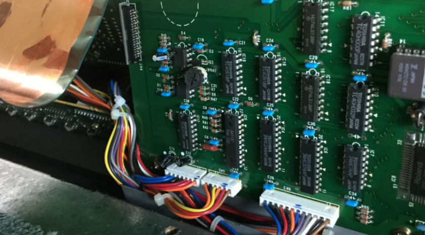
Replace R43 with a 100k variable PCB mount resistor
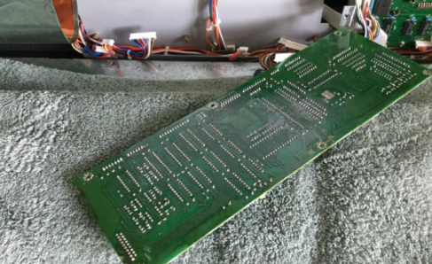
There’s no getting around it. Main Board A has to come out for desoldering. I’ve covered this process before. Six screws and several connectors need to be removed.
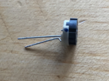
The odds of an alternative variable-resistance pressure membrane “just working” with the current 56k value seems unlikely. I obtained a small PCB-mount 100k resister and snipped off one of the outer legs. This gives us a replacement for R43 that will let us alter the resistance. I wasn’t sure this step was necessary but it seems prudent.
With that done, I re-assembled Main Board A back into position.
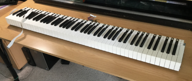
Remove the keybed assembly
Probably best to review my previous post on the subject.
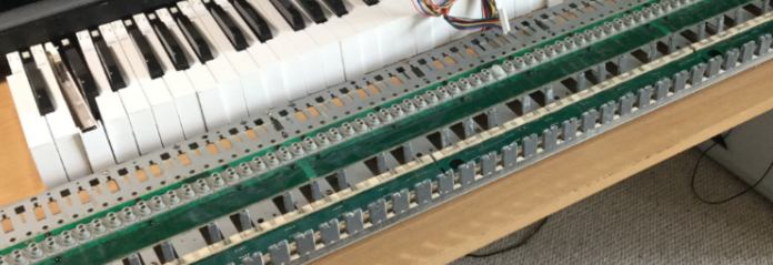
Digression: The Key Press Action
I created this animated GIF showing the mechanical action of a key press:
As you depress a key, the first thing that happens is that the grey rubber dome switch is activated. (You can see it on the right.) It has two contacts in it that closes two circuits in quick succession, indicating Note Velocity.
On the left you can see two felt strips that run under the keys. The black keys rest on the right-hand strip. The white keys rest on both strips. Under the felt strips are circuit contacts for each key press (white on the left, black on the right). Each contact is covered by a small rectangle of material that changes resistance with pressure. So, as you push down on the key, the resistance change is detected and translated to note pressure or “aftertouch”.
Remove the keys
This is where a key removal tool becomes very handy. I’ve actually made a short YouTube vid of the process:
With the keys removed, we can start finding out what is under those felt strips.
Remove the felt
At this point, my recommended procedure diverges from what I actually did. I was cautious and also not sure of what my next step would be. I wanted to remove the felt strip but leave the pressure strip in place. Also, I wasn’t planning on re-using the original felt strip, at least, not all of it. I figured I had a replacement strip that could be used for either the white keys or the black keys. I thought I only needed to keep 50% of the existing felt strips in re-usable condition.
The adhesive between the felt strip and the underlying plastic strip is quite strong and it was an awkward process to remove the felt intact while not also pulling the plastic strip away from the PCB. I really wanted to leave as much undisturbed and original as possible.
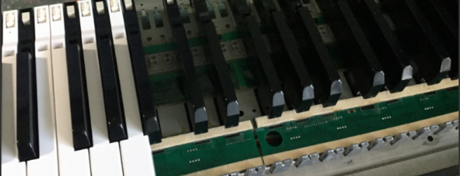
With the felt removed, we can see the plastic strips under which the pressure-sensitive resistive pads are mounted:
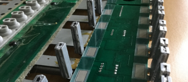
In hindsight, knowing that I was going to remove the plastic pressure strip eventually anyway, I should have removed the felt+plastic strip as a whole, and then carefully separated the felt from the plastic on a flat surface with more room to move.
Testing Substitute materials
I carefully cut out little rectangles of the Zoflex and Velostat material:
I then pried up the end of one of the plastic pressure strip and inserted the sample rectangles under it so that they covered the two carbon contacts beneath. Keys B7 and C8 were to be the test cases. I’m sorry, I don’t have a picture of this configuration, you’ll have to imagine it.
I then tacked the felt strip back in place temporarily and re-installed the two keys; lifted the key bed chassis back into place and re-connected it (remembering the aftertouch subsystem ribbon cable; easy to forget that one).
As a test patch, I initialized a program on the Novation PEAK and set the mod matrix so that aftertouch controlled the pitch of Osc1, bending it down a full octave at “maximum pressure”.
Results:
- The Zoflex key was unresponsive.
- The Velostat key was EXTREMELY sensitive to pressure.
Conclusion:
- Discard the Zoflex and experiment more with the Velostat.
WARNING: Turn off power to the A-80 before attempting to change the resistance of R43. Trust me. The A-80 will go berserk if you don’t.
By testing the change in touch response after each adjustment the value of R43, I could tell that reducing the resistance produced a corresponding decrease in sensitivity (a good thing!) A value of ~10k for R43 appeared to be optimal. Of course this will be subjective, your mileage may vary… I would think a varistor of 27k would probably give finer control.
What you shouldn’t do, and don’t need to know (Fast Forward)
- I used a crude method of tacking the Velostat rectangles in place
- I replaced the plastic pressure strips over the top and tacked them in place
- I used the 50% best original felt strips for the Black keys, flipping them over and using Kaisiking “red backed” double sided tape as adhesive.
- I used the brand new replacement felt strip for the White keys
- I assembled all of the key bed, and installed in the chassis
- I tested the unit.
- The Black keys worked great
- The White keys would not trigger reliably – the new felt + velostat was too thick, preventing the rubber domes from actuating.
- Also the difference in feel between white and black keys was disturbing.
- Removed key bed from chassis, removed all white keys
- Removed felt strip, which took the plastic strip with it because of the super-tacky double-sided tape I used
- Decided to use the remaining original felt strip for the white keys, and re-do the pressure strip “properly” while I was at it.
Converting the pressure strips
You should apply this process to both black and white keys.
Having peeled back and removed the plastic pressure strips, I carefully cleaned the carbon pads with 91% isopropyl alcohol.
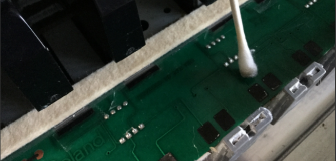
In the most-used keys (the central area), the original pressure pads had left white residue on the carbon pads. Use a light pressure and don’t go overboard, because you can remove carbon from the PCB and you don’t want to do that. Just clean them as much as you can, to encourage uniformity in touch response.
I then cleaned both sides of the plastic pressure strip with the isoprop, to remove as much of the residual sticky as possible.
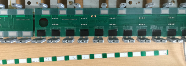
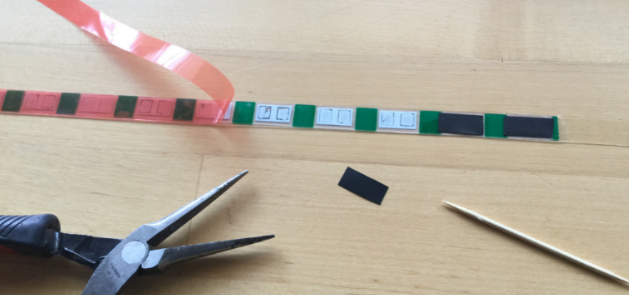
The next step was to apply the double-sided tape to the resistive side – the side that will be laid over the carbon contacts on the PCB.
Using tools to keep use of greasy fingers to a minimum, I peeled the backing from the tape and placed the rectangles of Velostat over the pressure pads:
Next steps:
- Carefully place the pressure strip back on to the PCB, locating it very carefully so that the pressure pads are over the carbon contacts for each key.
- Firmly burnish the strip in place to encourage the adhesive.
- Place a second layer of tape over the top surface of the plastic pressure strip (in hindsight, I could have done this before placing the Velostat rectangles.)
- Peel the backing, and place the original felt strip over the pressure strip.
- Re-install the white keys
And that’s it. Wonderfully responsive, polyphonic aftertouch.
The LCD display on my A-80 has always been a bit dim, but it is still usable. I think the backlight had dimmed over time, although I could still hear the whine of the voltage transformer that supplied it with power.
This noise is a known issue, and inspired by The Midi Maniac’s YouTube video, I ordered a replacement display from Gregor Walbeck E-Pianos in Germany. The part arrived in timely fashion, with very good instructions. Rather than re-create the excellent video, I’ll just add a few supplemental steps.
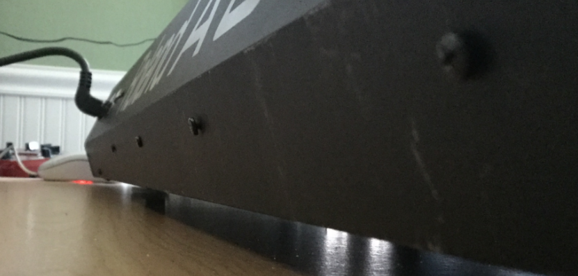
The standard first step for getting into the A-80 is to remove the screws from the underside in order to release the top panel and allow it to lift up and open. I’ve talked about this process before.
Having removed the 15 screws from the underside, but before opening the lid, there is another step that we need to do.
In order to reach the display sub-board, you will need to remove four screws that retain the metal sub-board chassis plate on which Main-A and Main-B pcb’s are mounted.
If you’re like me, you will have opened up the unit and discovered this plate is solidly attached by screws from the back of the unit:
These screws can be removed from the back side of the lid:
There is still one screw internally holding the plate in place, but it can be easily removed when the lid is open. I don’t have a picture of that, but you can see the MIDI Maniac removing it in his video. He doesn’t mention the four screws at the back, at all. They certainly add some stability to the internal circuit boards, but I can also see how they might have been added in a later production run, maybe.
Anyway – if your unit has these screws in the back, you will need to remove them. In my unit, these were two machine screws (outermost) and two self-tappers (innermost). I don’t know why they are different.
Word of warning: I had great difficulty re-inserting these screws. Aligning the mounting plate, then closing the lid in order to screw them in place was a trial. The threaded holes are in the mounting plate itself, not the thin back plate of the lid. There was no way to partially tighten the screws, then align the mounting plate on the points of the screws. I think if I had rotated the unit so that the lid was upright over the lip of the desk, I might have been able to re-fasten the screws while the lid was open. However, I persevered and eventually got it all tightened up.
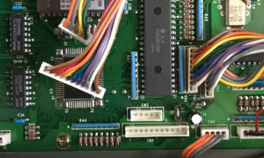
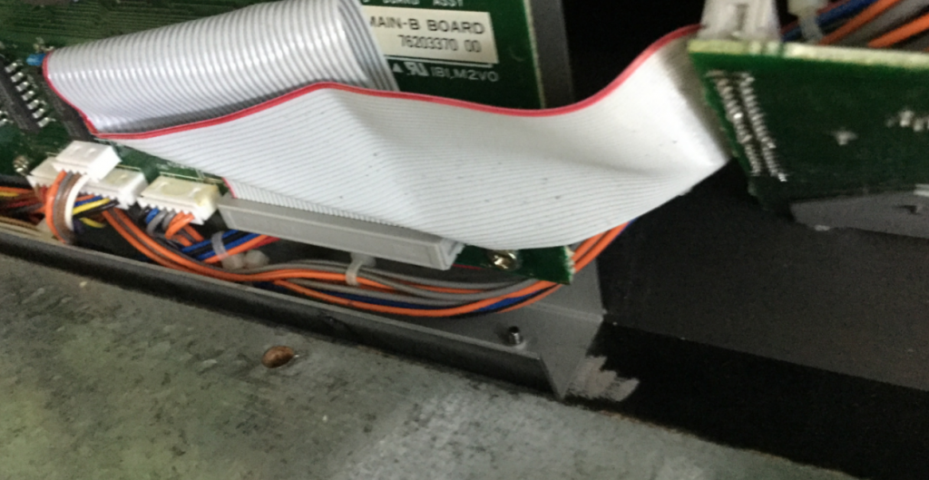
Then, disconnect CN3 and CN4 from Main-A board. I needed to disconnect them to create some slack. Now, after unscrewing the single retainer screw in the center of the board, you can carefully tilt the mounting plate towards you to gain access to the display sub-board, nestled into its recess.
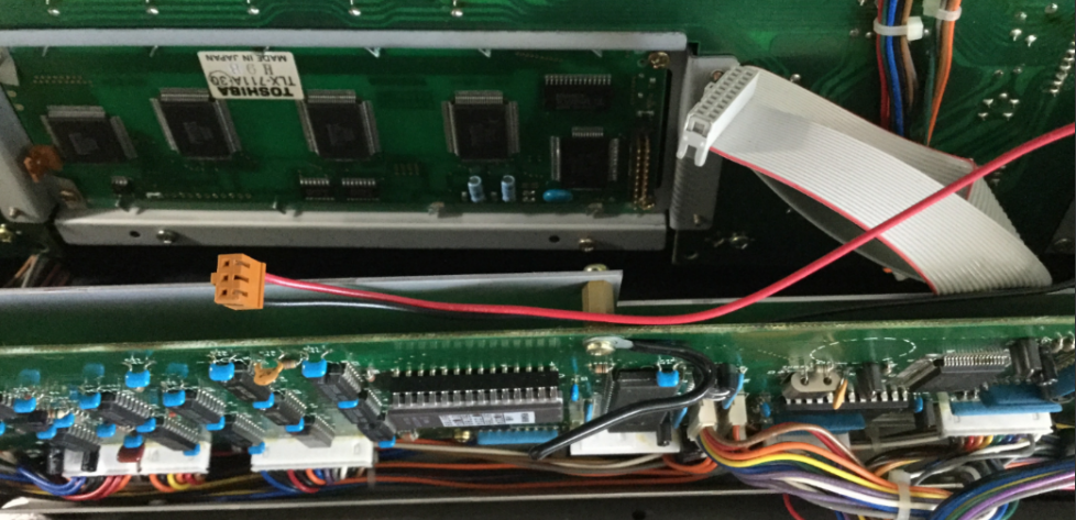
There are two connectors to remove from the display pcb: Power, and the ribbon cable. The display unit is retained by four screws, one in each corner. The only problematic one is the lower right, which I had to approach from under the bottom of the main boards’ mounting plate. There was only just enough clearance for an awkward operation. Not ideal, but I didn’t want to disassemble more than I absolutely had to.
The replacement display comes with eight plastic washers. I assumed that, due to the slightly thicker profile of the new unit, that these should be placed on either side of the pcb, so that the board was very slightly raised further out from the plexiglass window, and also protected from the head of each screw.
Okay, MIDI Maniac shows this reasonably well in his video, but in words: I inserted the screws on the right side, with the washers in place, loosely so that I could slide the new display board in from the left (the mounting holes in the PCB are actually slots). Then, using double-sided tape to hold the plastic washers on either side of the PCB, I could rotate the display into place, and then insert the screws on the left side and tighten them all up. (Remember to remove the sticky protection label from the top of the new screen before doing this!)
Then, simply attach the ribbon cable to the board. As per instructions, it does not need the power connector. This can be un-threaded back to the PSU board and curled up and zip-tied out of the way.
Now for testing:
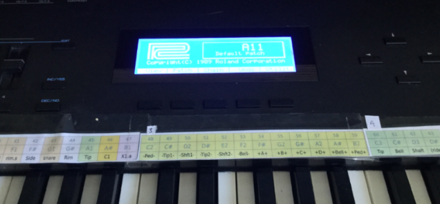
Worked first time. Yay. Now the instructions are very clear about how to remove the two components on the PSU board that are no longer required to deliver power to the display. I snipped them off with a pair of nipper pliers. No More High-pitched whine!
Recent Comments