The LCD display on my A-80 has always been a bit dim, but it is still usable. I think the backlight had dimmed over time, although I could still hear the whine of the voltage transformer that supplied it with power.
This noise is a known issue, and inspired by The Midi Maniac’s YouTube video, I ordered a replacement display from Gregor Walbeck E-Pianos in Germany. The part arrived in timely fashion, with very good instructions. Rather than re-create the excellent video, I’ll just add a few supplemental steps.
The standard first step for getting into the A-80 is to remove the screws from the underside in order to release the top panel and allow it to lift up and open. I’ve talked about this process before.
Having removed the 15 screws from the underside, but before opening the lid, there is another step that we need to do.
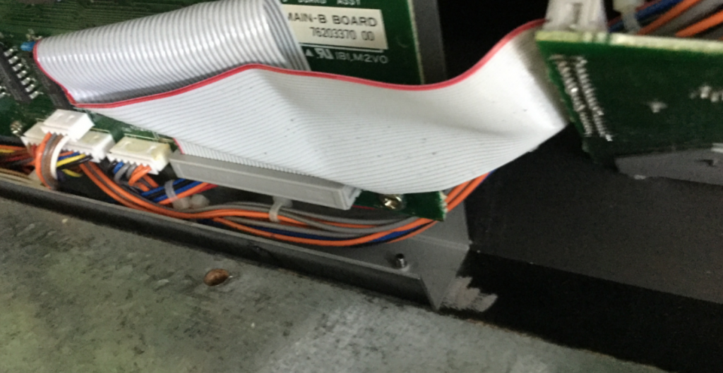
In order to reach the display sub-board, you will need to remove four screws that retain the metal sub-board chassis plate on which Main-A and Main-B pcb’s are mounted.
If you’re like me, you will have opened up the unit and discovered this plate is solidly attached by screws from the back of the unit:
These screws can be removed from the back side of the lid:
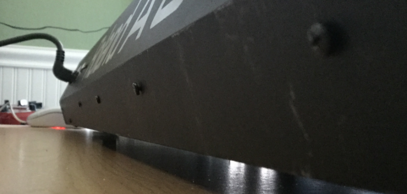
There is still one screw internally holding the plate in place, but it can be easily removed when the lid is open. I don’t have a picture of that, but you can see the MIDI Maniac removing it in his video. He doesn’t mention the four screws at the back, at all. They certainly add some stability to the internal circuit boards, but I can also see how they might have been added in a later production run, maybe.
Anyway – if your unit has these screws in the back, you will need to remove them. In my unit, these were two machine screws (outermost) and two self-tappers (innermost). I don’t know why they are different.
Word of warning: I had great difficulty re-inserting these screws. Aligning the mounting plate, then closing the lid in order to screw them in place was a trial. The threaded holes are in the mounting plate itself, not the thin back plate of the lid. There was no way to partially tighten the screws, then align the mounting plate on the points of the screws. I think if I had rotated the unit so that the lid was upright over the lip of the desk, I might have been able to re-fasten the screws while the lid was open. However, I persevered and eventually got it all tightened up.
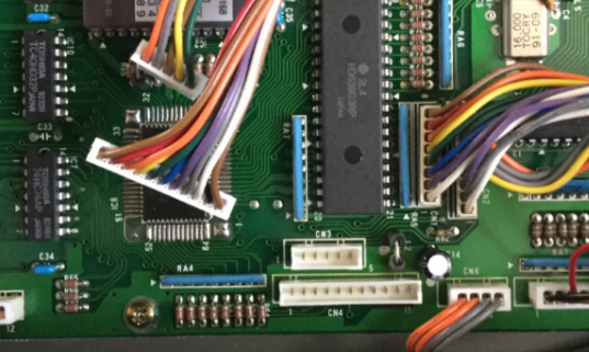
Then, disconnect CN3 and CN4 from Main-A board. I needed to disconnect them to create some slack. Now, after unscrewing the single retainer screw in the center of the board, you can carefully tilt the mounting plate towards you to gain access to the display sub-board, nestled into its recess.
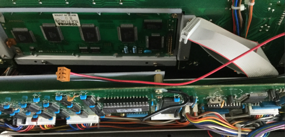
There are two connectors to remove from the display pcb: Power, and the ribbon cable. The display unit is retained by four screws, one in each corner. The only problematic one is the lower right, which I had to approach from under the bottom of the main boards’ mounting plate. There was only just enough clearance for an awkward operation. Not ideal, but I didn’t want to disassemble more than I absolutely had to.
The replacement display comes with eight plastic washers. I assumed that, due to the slightly thicker profile of the new unit, that these should be placed on either side of the pcb, so that the board was very slightly raised further out from the plexiglass window, and also protected from the head of each screw.
Okay, MIDI Maniac shows this reasonably well in his video, but in words: I inserted the screws on the right side, with the washers in place, loosely so that I could slide the new display board in from the left (the mounting holes in the PCB are actually slots). Then, using double-sided tape to hold the plastic washers on either side of the PCB, I could rotate the display into place, and then insert the screws on the left side and tighten them all up. (Remember to remove the sticky protection label from the top of the new screen before doing this!)
Then, simply attach the ribbon cable to the board. As per instructions, it does not need the power connector. This can be un-threaded back to the PSU board and curled up and zip-tied out of the way.
Now for testing:
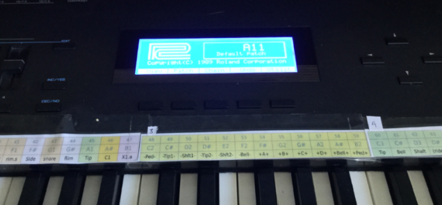
Worked first time. Yay. Now the instructions are very clear about how to remove the two components on the PSU board that are no longer required to deliver power to the display. I snipped them off with a pair of nipper pliers. No More High-pitched whine!
Leave a Reply