Since our AI overlords started exercising their self-granted right to non-consensually devour the Internet for their own theoretical future monetary gains, I haven’t really felt like sharing content on the web.
I will say this: If you would like to know how to open up the Arturia Keylab 61 Mk II and mess around with the pitch wheel – specifically inverting the polarity – then feel free to get in touch.
Use Velostat to replace the pressure-sensitive cells under each key.
Change R43 to a variable resistor of about 27k and set it mid-way
Enjoy.
The longer, illustrated version
Despite the R43 fix, the touch response has never really been usable. The mechanism Roland used clearly didn’t remain viable over time. The risk of screwing up the key bed completely has always deterred me from experimenting in this area.
And then, there was this thread on Computer Music Guide forum, “Roland A-80 (Aftertouch Repair)”. Back in 2014, noisevoid had the great idea to experiment with alternative pressure-sensitive rubber to see if they could restore touch-sensitivity to the notoriously unresponsive A-80 key bed. Their research identified a product from Zoflex as a possible solution…. and then they were never heard from again on that thread.
But the idea intrigued me, and after Syntaur alerted me that the “upper” key felt strip was back in stock, I decided it was time to go deeper. I placed an order for a sheet of the Zoflex product… and also did more research on pressure-sensitive materials.
One finding in particular looked very interesting: In 2016 Liam Lacey had implemented a “toy keyboard synthesizer” with pressure sensitivity using a product called “Velostat”. Intrigued, I ordered a sheet as an alternative.
Eventually the samples showed up. The Zoflex rubber sheet was about 1mm thick and quite “spongy” and quite expensive for a 10cm square sample, in beige. The Velostat sheet was larger, more like an A4 sheet of paper, and much thinner. And cheaper.
Here’s the plan:
Replace R43 with a variable resistor to allow for sensitivity adjustment
Remove the keys and the upper felt strips
Lift the plastic pressure strips enough to insert samples of alternate product
re-assemble loosely to test response
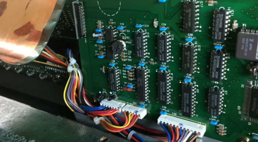
Replace R43 with a 100k variable PCB mount resistor
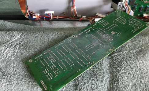
There’s no getting around it. Main Board A has to come out for desoldering. I’ve covered this process before. Six screws and several connectors need to be removed.
100k PCB mount, minus one leg
The odds of an alternative variable-resistance pressure membrane “just working” with the current 56k value seems unlikely. I obtained a small PCB-mount 100k resister and snipped off one of the outer legs. This gives us a replacement for R43 that will let us alter the resistance. I wasn’t sure this step was necessary but it seems prudent.
R43 now can be adjusted from 0 – 100k
With that done, I re-assembled Main Board A back into position.
Now you know where most of that weight comes from. It’s as heavy as heck.
Digression: The Key Press Action
I created this animated GIF showing the mechanical action of a key press:
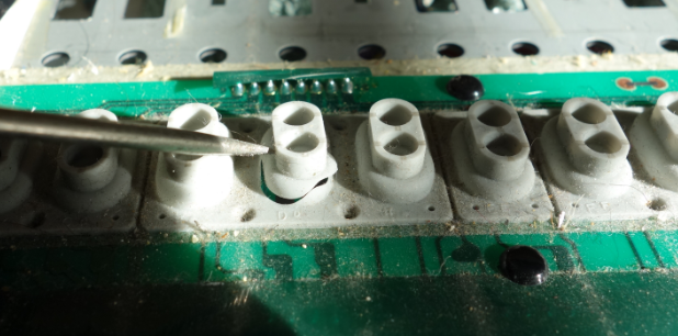
Before and After key press
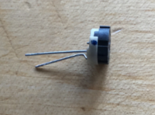
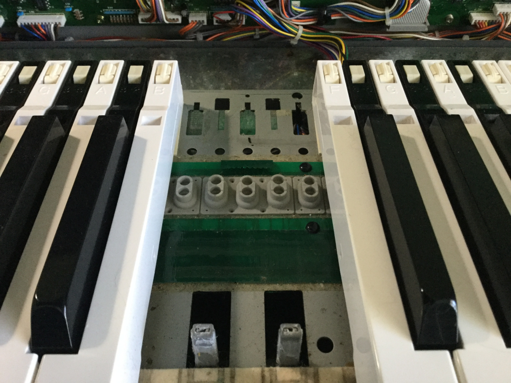
As you depress a key, the first thing that happens is that the grey rubber dome switch is activated. (You can see it on the right.) It has two contacts in it that closes two circuits in quick succession, indicating Note Velocity.
On the left you can see two felt strips that run under the keys. The black keys rest on the right-hand strip. The white keys rest on both strips. Under the felt strips are circuit contacts for each key press (white on the left, black on the right). Each contact is covered by a small rectangle of material that changes resistance with pressure. So, as you push down on the key, the resistance change is detected and translated to note pressure or “aftertouch”.
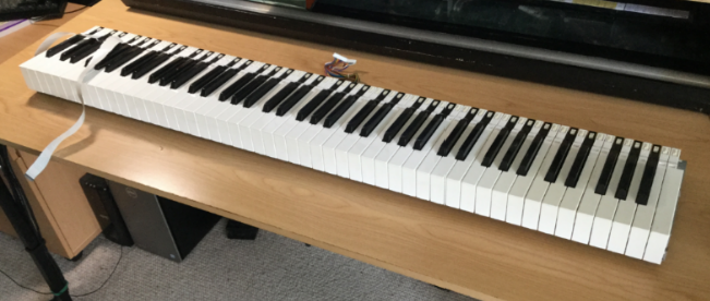
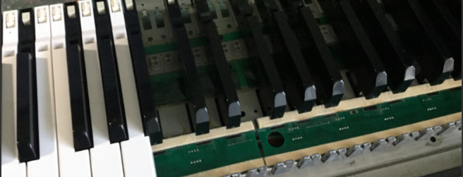
Remove the keys
This is where a key removal tool becomes very handy. I’ve actually made a short YouTube vid of the process:
With the keys removed, we can start finding out what is under those felt strips.
A lot easier to manage without that key weight.
Remove the felt
At this point, my recommended procedure diverges from what I actually did. I was cautious and also not sure of what my next step would be. I wanted to remove the felt strip but leave the pressure strip in place. Also, I wasn’t planning on re-using the original felt strip, at least, not all of it. I figured I had a replacement strip that could be used for either the white keys or the black keys. I thought I only needed to keep 50% of the existing felt strips in re-usable condition.
The adhesive between the felt strip and the underlying plastic strip is quite strong and it was an awkward process to remove the felt intact while not also pulling the plastic strip away from the PCB. I really wanted to leave as much undisturbed and original as possible.
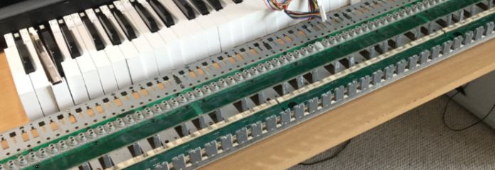
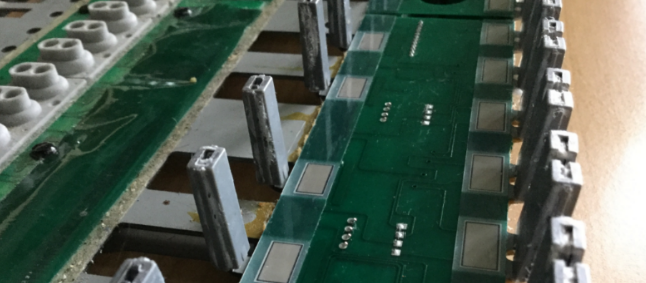
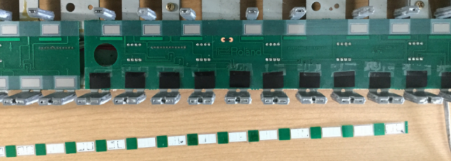
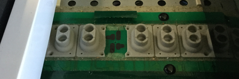
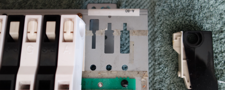
With the felt removed, we can see the plastic strips under which the pressure-sensitive resistive pads are mounted:
Black keys on the left, White keys on the right
In hindsight, knowing that I was going to remove the plastic pressure strip eventually anyway, I should have removed the felt+plastic strip as a whole, and then carefully separated the felt from the plastic on a flat surface with more room to move.
Testing Substitute materials
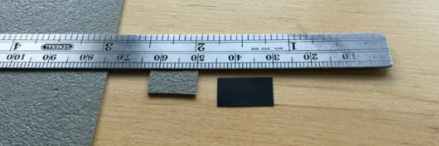
I carefully cut out little rectangles of the Zoflex and Velostat material:
The Velostat is paper-thin. The Zolfex, not so much
I then pried up the end of one of the plastic pressure strip and inserted the sample rectangles under it so that they covered the two carbon contacts beneath. Keys B7 and C8 were to be the test cases. I’m sorry, I don’t have a picture of this configuration, you’ll have to imagine it.
I then tacked the felt strip back in place temporarily and re-installed the two keys; lifted the key bed chassis back into place and re-connected it (remembering the aftertouch subsystem ribbon cable; easy to forget that one).
As a test patch, I initialized a program on the Novation PEAK and set the mod matrix so that aftertouch controlled the pitch of Osc1, bending it down a full octave at “maximum pressure”.
Results:
The Zoflex key was unresponsive.
The Velostat key was EXTREMELY sensitive to pressure.
Conclusion:
Discard the Zoflex and experiment more with the Velostat.
WARNING: Turn off power to the A-80 before attempting to change the resistance of R43. Trust me. The A-80 will go berserk if you don’t.
By testing the change in touch response after each adjustment the value of R43, I could tell that reducing the resistance produced a corresponding decrease in sensitivity (a good thing!) A value of ~10k for R43 appeared to be optimal. Of course this will be subjective, your mileage may vary… I would think a varistor of 27k would probably give finer control.
What you shouldn’t do, and don’t need to know (Fast Forward)
I used a crude method of tacking the Velostat rectangles in place
I replaced the plastic pressure strips over the top and tacked them in place
I used the brand new replacement felt strip for the White keys
I assembled all of the key bed, and installed in the chassis
I tested the unit.
The Black keys worked great
The White keys would not trigger reliably – the new felt + velostat was too thick, preventing the rubber domes from actuating.
Also the difference in feel between white and black keys was disturbing.
Removed key bed from chassis, removed all white keys
Removed felt strip, which took the plastic strip with it because of the super-tacky double-sided tape I used
Decided to use the remaining original felt strip for the white keys, and re-do the pressure strip “properly” while I was at it.
Converting the pressure strips
You should apply this process to both black and white keys.
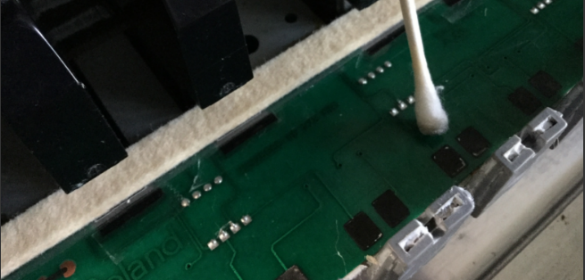
Having peeled back and removed the plastic pressure strips, I carefully cleaned the carbon pads with 91% isopropyl alcohol.
In the most-used keys (the central area), the original pressure pads had left white residue on the carbon pads. Use a light pressure and don’t go overboard, because you can remove carbon from the PCB and you don’t want to do that. Just clean them as much as you can, to encourage uniformity in touch response.
I then cleaned both sides of the plastic pressure strip with the isoprop, to remove as much of the residual sticky as possible.
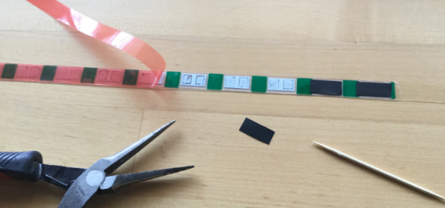
The next step was to apply the double-sided tape to the resistive side – the side that will be laid over the carbon contacts on the PCB.
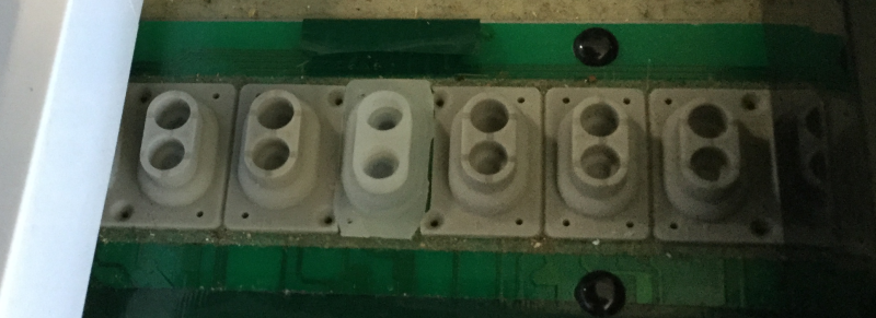
Using tools to keep use of greasy fingers to a minimum, I peeled the backing from the tape and placed the rectangles of Velostat over the pressure pads:
The tape extends beyond the end of the strip, to keep it from moving about during the placement process
Next steps:
Carefully place the pressure strip back on to the PCB, locating it very carefully so that the pressure pads are over the carbon contacts for each key.
Firmly burnish the strip in place to encourage the adhesive.
Place a second layer of tape over the top surface of the plastic pressure strip (in hindsight, I could have done this before placing the Velostat rectangles.)
Peel the backing, and place the original felt strip over the pressure strip.
Re-install the white keys
And that’s it. Wonderfully responsive, polyphonic aftertouch.
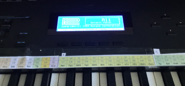
The LCD display on my A-80 has always been a bit dim, but it is still usable. I think the backlight had dimmed over time, although I could still hear the whine of the voltage transformer that supplied it with power.
This noise is a known issue, and inspired by The Midi Maniac’s YouTube video, I ordered a replacement display from Gregor Walbeck E-Pianos in Germany. The part arrived in timely fashion, with very good instructions. Rather than re-create the excellent video, I’ll just add a few supplemental steps.
The standard first step for getting into the A-80 is to remove the screws from the underside in order to release the top panel and allow it to lift up and open. I’ve talked about this process before.
Having removed the 15 screws from the underside, but before opening the lid, there is another step that we need to do.
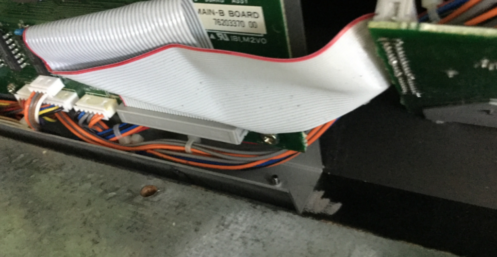
In order to reach the display sub-board, you will need to remove four screws that retain the metal sub-board chassis plate on which Main-A and Main-B pcb’s are mounted.
If you’re like me, you will have opened up the unit and discovered this plate is solidly attached by screws from the back of the unit:
You can see the shaft of the right-most screw poking up from the back.
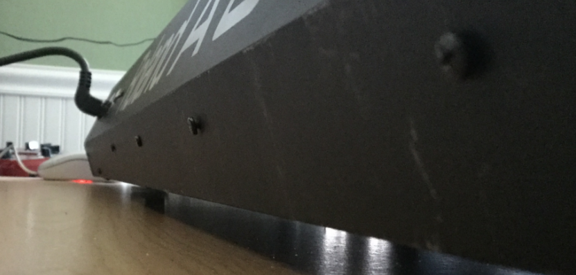
These screws can be removed from the back side of the lid:
Ideally, remember which screw was in each location, because on my unit, they were two different types!
There is still one screw internally holding the plate in place, but it can be easily removed when the lid is open. I don’t have a picture of that, but you can see the MIDI Maniac removing it in his video. He doesn’t mention the four screws at the back, at all. They certainly add some stability to the internal circuit boards, but I can also see how they might have been added in a later production run, maybe.
Anyway – if your unit has these screws in the back, you will need to remove them. In my unit, these were two machine screws (outermost) and two self-tappers (innermost). I don’t know why they are different.
Word of warning: I had great difficulty re-inserting these screws. Aligning the mounting plate, then closing the lid in order to screw them in place was a trial. The threaded holes are in the mounting plate itself, not the thin back plate of the lid. There was no way to partially tighten the screws, then align the mounting plate on the points of the screws. I think if I had rotated the unit so that the lid was upright over the lip of the desk, I might have been able to re-fasten the screws while the lid was open. However, I persevered and eventually got it all tightened up.
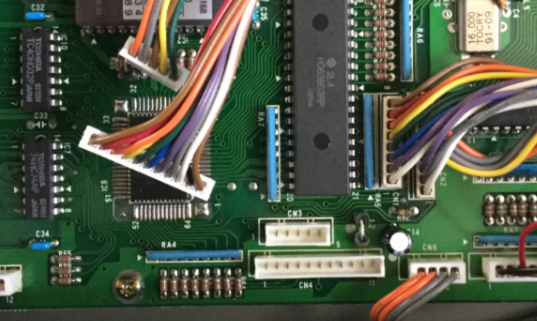
Then, disconnect CN3 and CN4 from Main-A board. I needed to disconnect them to create some slack. Now, after unscrewing the single retainer screw in the center of the board, you can carefully tilt the mounting plate towards you to gain access to the display sub-board, nestled into its recess.
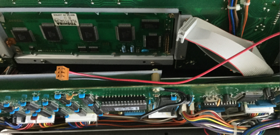
There are two connectors to remove from the display pcb: Power, and the ribbon cable. The display unit is retained by four screws, one in each corner. The only problematic one is the lower right, which I had to approach from under the bottom of the main boards’ mounting plate. There was only just enough clearance for an awkward operation. Not ideal, but I didn’t want to disassemble more than I absolutely had to.
The replacement display comes with eight plastic washers. I assumed that, due to the slightly thicker profile of the new unit, that these should be placed on either side of the pcb, so that the board was very slightly raised further out from the plexiglass window, and also protected from the head of each screw.
Okay, MIDI Maniac shows this reasonably well in his video, but in words: I inserted the screws on the right side, with the washers in place, loosely so that I could slide the new display board in from the left (the mounting holes in the PCB are actually slots). Then, using double-sided tape to hold the plastic washers on either side of the PCB, I could rotate the display into place, and then insert the screws on the left side and tighten them all up. (Remember to remove the sticky protection label from the top of the new screen before doing this!)
Then, simply attach the ribbon cable to the board. As per instructions, it does not need the power connector. This can be un-threaded back to the PSU board and curled up and zip-tied out of the way.
Now for testing:
The new display in action (not as bright as it appears here)
Worked first time. Yay. Now the instructions are very clear about how to remove the two components on the PSU board that are no longer required to deliver power to the display. I snipped them off with a pair of nipper pliers. No More High-pitched whine!
So, either I have to pivot to writing music without D above middle C, or I have to repair my Roland A-80 again. The D4 key stopped responding. After a miserable couple of days procrastinating, I opened her up and took a look.
I’ve written about disassembling the A-80 keybed before, and of course the first thing I did was open that post and refresh my memory. Quick recap for first-time readers:
The A-80 is HEAVY and most of that is in the keybed itself;
It uses a rubber dome with two contact switches to trigger a velocity-weighted note event from each key press.
One thing I was sure about: After last time, I wasn’t going to try and lift the entire keyboard off the table, and also I was going to need to have it in a state where I could monitor MIDI output whilst testing key presses.
I pulled the keyboard out and unplugged it, then tilted it onto its back edge (on a soft towel) and removed the necessary 15 screws from the underside.
Fig.1 – Those 15 screws (marked I) need to come out.
Right-side up, carefully lifted the lid. At this point I deviated from the previous process – I needed this to be in a playable state whilst examining the inner workings of the keybed. I unscrewed the 12 screws holding the keybed in position in the chassis (shown as II and III in the diagram above – III from inside the chassis, and II from underside. Then I lifted the keybed away from the lip of the chassis and raised it up on two metal blocks (about an inch high) on either side. This was sufficient to be able to remove the white keys whilst leaving all the connectors in place.
The key removal tool made quick work of removing the keys around the problematic “D”:
Fig.2 – C4 -> E4 removed, revealing the strip of rubber domes and a “!” mark
Not the sharpest knife in the draw, am I. When I saw that “!” in black sharpie on the base plate, I remembered from last time: D4 was the key in which I accidently damaged the rubber dome. I left it unrepaired last time, because it sat correctly, the invisible slit in the side of the dome didn’t appear to affect the key response. (And, indeed, it worked fine for 6 months.) Yet, here we are.
This was a great relief, to know that there was an actual root cause to the failure of D4, and not just something random breaking.
So, what to do? First, I tried repairing the slit (which was substantially larger than I remember) with superglue.
THIS WAS A BAD IDEA.
A) it doesn’t seem to bond the rubber dome together, and B) very great danger of getting glue on the conductive contacts under the dome or on the PCB. NEVER TRY THIS.
At this point, if I had no other recourse, I was prepared to re-purpose the rubber dome from the lowest or highest note, sacrificing it and yielding a functional 87-note keybed.
I had one more thing to try, however: Replacement rubber domes from www.bustedgear.com. I haven’t found any genuine article for the Roland A-80 in stock anywhere, but these replacement parts KCS10 are apparently good for the A-50 and they sure looked near-as-dammit identical. I’d ordered a couple of sets several months ago, on a hunch that I might need them in the future. THE FUTURE IS NOW
Using an exacto blade, I carefully removed the damaged D4 dome. The domes are installed as a strip, held in place by double-sided tape (true!) and the white key domes are subtly different from the black keys. Upon close examination of the replacement, I could see they weren’t an exact match with either black or white key dome, but I think they would be close enough. Anyway, the bad dome had to come out, even if I was to replace it with a dome from elsewhere in the keybed. It was worth trying these KCS10 domes, just to see.
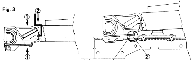
Fig.3 – surgery complete
Trimming the replacement dome to fit was finicky but the exacto blade earned its name. The replacement dome is slightly lower (not easy to see from this angle):
Fig.4 – Transplant in place
I carefully installed the D4 making sure not to dislodge the new dome, just sitting in place with the slightly tacky and very dusty tape remaining on the PCB.
Connect mains power and MIDI out, open Cakewalk with an instance of Pianoteq responding to notes, and HOT DAMN if it didn’t JUST WORK. Perfect? Pretty close. It does seem to respond a little “hotter” in terms of velocity sensitivity, which makes sense if the new dome is slightly lower/closer to the PCB. But you know what? The velocity sensitivity across the whole keybed has some variation in it, and this is DEFINITELY playable. It’s not wrong; it’s just slightly different. Not really noticeable unless I listen carefully.
Let me be more clear: I can forsee a time when I a) experiment with replacing a Black key dome, and if that works okay, then b) replacing the whole 7+octaves. That would give the A-80 a usable and consistent velocity response.
Okay, um, let’s take the key out and try and attach that dome in place a little more firmly. I used two tiny pieces of fresh double-sided tape and I guess it made a slight difference. Probably not a great idea, if one of the strips comes loose, it could work its way up or down to cover the contacts under the dome, and then this key will stop responding again. At least I will know how to fix it.
Fig.5 – The Damaged Dome, with traces of the failed superglue fix
All keys back in place, keybed restored to original position, all screwed together, and hey we’re good for another take.
I can not remember when I acquired the Roland A-880 MIDI Patch Bay. It certainly wasn’t the first piece of kit I ever bought – that honor goes to a second-hand Roland Jupiter 6 back in 1988. It had some DIN ports – In and Out – on the back for something called MIDI. It was soon followed by an Akai sampling keyboard and synthesizer rack module, which worked very well together when connected with MIDI cables. Also, you could send notes from the Jupiter to the Akai devices over MIDI, so long as you set the rack to listen on MIDI Channel 1 or 2. Shortly after that, we found a Roland MIDI Interface (MPU-401?) for our PC, and started recording MIDI sequences into a copy of Passport Software’s Master Tracks Pro.
Recap: MIDI in a nutshell
So far, so good. We had PC software that allowed us to perform patch librarian tasks using MIDI (called System Exclusive or SYSEX) on many of the devices but it requires bi-directional data transfer between the sound module and the computer, and signals in a single MIDI cable only go one way: You need two cables connecting the In and Out ports. From the computer OUT to the module IN; and also from the module OUT to the computer IN. The computer requests data; the module sends it; the computer sends more data.
MIDI messages are assigned a “channel” between 1 and 16. So if you connect a MIDI cable between two devices, a device listening on channel 1 won’t respond to any messages assigned to channels 2-16. More information here.
This allows more than one device in a MIDI chain. In fact, later keyboards and modules included a third port, a MIDI THRU that would re-transmit incoming MIDI signals to the next device in a chain, allowing layering and multi-timbral setups. Some manufacturers combined the THRU and OUT connectors.
I realize as I write this that it all sounds archaic these days, when we have digital bi-directional comms over a single USB connector, let alone Ethernet and WiFi. But back in the 1990’s, it was like magic, and no-one complained that they needed two cables for this type of two-way communication.
The problem is that the more devices you have, the more un-plugging and re-plugging of MIDI cables is required to manage all the equipment. Some sort of automated patch bay becomes almost required. Enter the Roland A-880 MIDI Patch Bay.
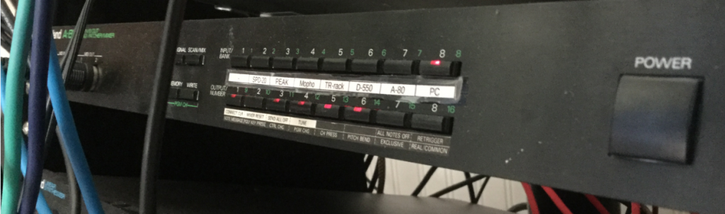
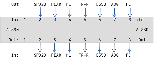
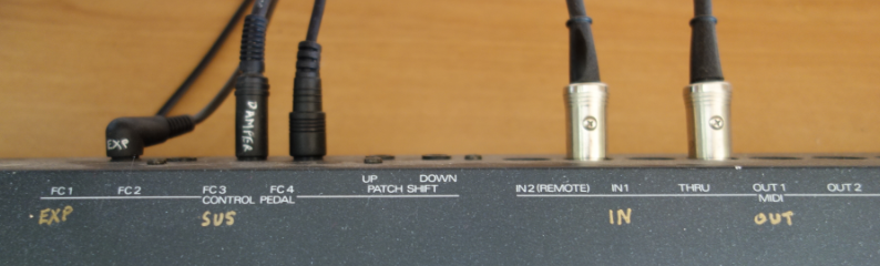
Fig 2. Front panel controls of the Roland A-880
The A-880 is basically a box with 8 inputs; 8 outputs; and it will connect these together any way you like. You can use it ad-hoc by selecting an input (from the top row of eight buttons) and then selecting which of the eight outputs (from the bottom row of buttons) the MIDI messages are echoed on. If you find yourself using the same set of connections over and over, you can save it in one of the 64 possible memory locations for easy recall.
The Studio Equipment
For the purposes of this article I’m using the following devices:
Windows 10 computer running the Cakewalk by Bandlab DAW
MIDISport 2×2 USB MIDI interface (ports A and B)
Roland A-80 Keyboard controller
Roland SPD-20 Drum Pad controller
Novation PEAK synthesizer desktop module
Korg M1 Synthesizer keyboard
Korg TR-Rack synthesizer rack module
Roland D-550 synthesizer rack module
All these devices have MIDI In and Out ports for sending and receiving MIDI messages such as notes, clock, and system-exclusive (data dumps and patch edits). I’ve already decided which MIDI channels each device is going to use.
Aside: Cakewalk and MIDI Echo
Cakewalk – and presumably other DAWs – has the ability to mimic the behavior of a THRU port, and echoing the incoming MIDI data from input to output. It records the performance into the active track, but also optionally echoes the notes through the computer’s MIDI output port. This lets me play the Roland A-80 whilst hearing the sound from, say, the Roland D-550.
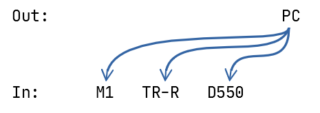
Use Case 1 – Playback of a previously recorded MIDI project from the DAW
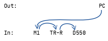
It’s an old project from back before we had the ability to record Audio tracks in our computer. It has three tracks and I need to send the MIDI out to the Korg M1; the Roland D-550; and the third track was drums and there’s a nice standard kit on the TR-Rack that will do nicely. So I need to connect the MIDI OUT from the computer to the MIDI In on those three modules:
Unfortunately, that arrangement can’t be done as-is because the MIDI cables are point-to-point: one Out port has to go to one In port. Instead, we have to daisy-chain them using the MIDI THRU ports on each unit:
That works – providing you have the THRU ports available.
One down-side of this is latency, in that if your chain has too many hops, then the instrument at the end of the chain can take a noticeable time to respond after you press a note. Also, there’s a potential for signal degradation. If you limit yourself to 2-3 devices in a chain, it’s not a problem, and it works.
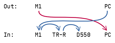
Use Case 2 – Recording a performance into a new MIDI track
Now I want to record a MIDI performance on the M1 keyboard into a new track in the project in the computer software. So I need to connect the M1 Out to the computer’s In:
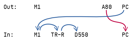
Hang on, the M1 keyboard is great for some types of playing styles, but after some practice runs, I think I really want to use the weighted, 88-keys of my Roland A-80. Just a sec, I need to re-connect:
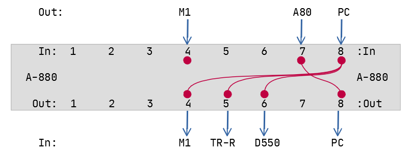
Okay, enough! I’m sure you get the idea. Let’s move all these connections into the Roland A-880. One advantage is that now, we can feed multiple In ports from a single Out port, reducing the latency and signal degradation (which in practice isn’t a problem, but hey, it’s all good):
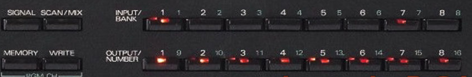
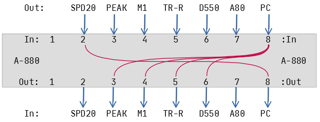
Bank/Patch 1:7 with A-80 as controller
Making virtual connections between the ports is easy once you know how: Press a button on the top row, followed by one or more buttons on the bottom row. Then press Scan/Mix or Signal to complete the configuration. So to set it up as shown above:
Press In-8
Press Out-4, Out-5, Out-6
Press In-7
Press Out-8
Now I can send my performance on the A-80 to the Cakewalk DAW running on my computer; and in turn, Cakewalk sends the MIDI notes from the existing tracks out to my sound modules.
If I decide I’d like to record the next track on the Korg M1, I can merely switch from the A-80 by:
Press In-4
Press Out-8 (this “disconnects” the previous connection from In-7)
Now the M1 is the “controller”.
Connecting the rest of the gear
Now we go into the closet and pull out ALL the MIDI cables, and connect all the devices:
Ports 1 and 2 are accessible from the front panel of the A-880, so I tend to reserve these for “temporary” connections (although, my SPD-20 drum pad controller has been out of the closet and connected up for about a year now). Port 1 is handy when I want to integrate my iPad into the studio, or back up patches on the Line6 POD.
Now, it is so easy to lay down a new drum track using the SPD-20 as the controller:
Bank/Patch 1:2 with SPD-20 as controller
Other features
MIDI Clock is a “pulse” or timing reference transmitted along with other data that can be used to synchronize devices. The A-880 will respect the MIDI Clock on the port nominated as “Control In”. You can set which port (1-8) is the “control” by holding down the corresponding input button during power-on. I use Port 8 as the Control In because the PC/DAW is my timing master.
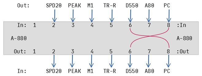
Use Case 3 – D-550 Editor/Librarian operation
I can use SoundQuest‘s MIDI Quest software to download, edit, and upload patches to the Roland D-550, and this requires that we connect both In and Out to the computer:
Bank/Patch 8:6 for SyEx/Dump from the D-550
This works well – I can request a dump from inside MIDI Quest, and edit the patches, but what if I want to try out a few riffs from my handy keyboard controller? I want to be able to both edit the D-550 patches from the Computer (PC on Port 8) and also play notes on, say, the Korg M1 keyboard (Port 4), and have the D-550 respond.
Normally, MIDI does not allow multiple IN ports to direct to a common OUT port.
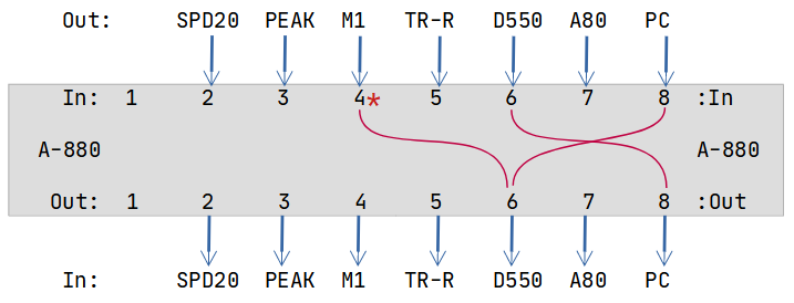
This is where the A-880’s Mixing function comes in: Any additional input port can be mixed with the control port. By design, Port 8 is my control port and also used by the DAW/PC. So we can add the M1 keyboard into the configuration using these steps:
Hold down the Scan/Mix button;
Press In-4 (the Korg M1);
Press Out-6 (the Roland D-550);
Release the Scan/Mix button.
That might seem odd but when you see the configuration graphically, hopefully it will make sense:
Mixing in signals from the M1 to audition sounds on the D-550
You can tell that Port 4 is “mixed” because the LED will flash during the scan cycle.
Memory Management
We have 64 memory locations available in 8 banks of 8 patches. I can’t imagine needing all of them. I divide mine into two categories: Bank 1 is “Controller select”, and Bank 8 is “SysEx Operation”. To make it easy to remember, I use the patch number to indicate the “subject” of the configuration:
1:2 SPD-20 is controller (on port 2)
1:4 Korg M1 is controller (on port 4)
1:7 Roland A-80 is controller (on port 7)
8:2 SysEx/Dump for SPD-20 (on port 2)
8:4 SysEx/Dump for Korg M1 (on port 4)
etc
You can change programs on the A-880 by sending it patch change messages on the Control In port, using the Control MIDI Channel. You set this channel by pressing Memory + Write , then one of the 16 input/output buttons. For example, to set a control channel of 12:
Press MEMORY + WRITE (don’t hold)
Press OUTPUT 4
Press SCAN/MIX or SIGNAL to complete.
Final thoughts
The A-880 has remained the heart of my studio since arriving back in the early 1990’s. Keyboards come and go (a moment of silence for the Jupiter 6, alas) but the A-880 remains at the hub, probably the most reliable piece of gear I’ve ever owned.
This post is mostly for my own reference, and also to replace and supplement information that used to be hosted at http://soundofmusic.se/ but is no longer available.
According to Gearslutz, the A-80 features a Matsushita SK-688 keybed – it’s an older keybed (but it checks out) – and Syntaur have some replacement parts available, including a felt strip suitable for the keybed “lowers”, where the keys rest when they are not being played. I ordered two units, on a hunch (turns out I was right).
When they arrived, it was time to begin the service operation.
Before you begin
I highly recommend getting a copy of the service manual. I’ve saved you the bother of finding it: here it is. That’s the PDF I use, hosted on our site. (It’s not perfect but it is the best resolution and clearest copy I could find online.) I kept the PDF open on my desktop, and flipped between pages as I worked.
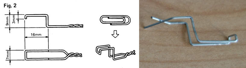
Secondly, you will need a key removal tool. There are instructions in the manual on Page 5 on how to make one using a paper clip, and providing you are able to match the dimensions specified, it actually works.
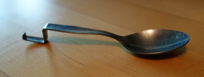
However, it is awkward to use, and not too robust for intensive use. (I went the extra mile and sacrificed a teaspoon for the cause. More on that later. If you don’t have access to a basic workshop, be assured that the paper clip tool does work.)
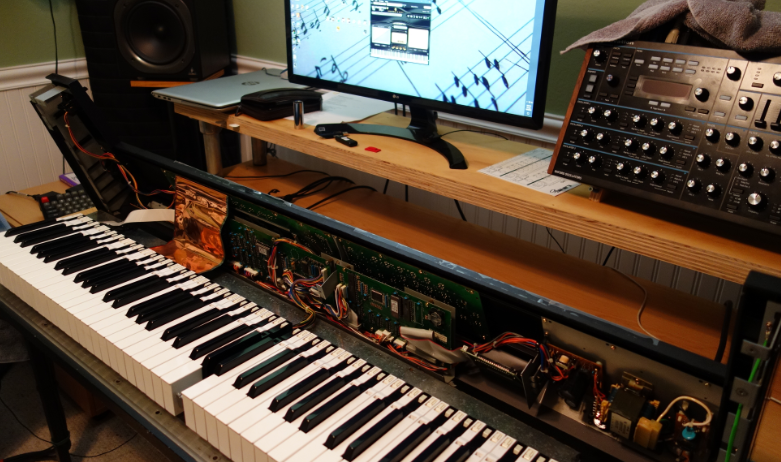
Before moving it to the work table, make a note of any connections
Wherever you move the unit to, make sure it is at a comfortable working height. I initially placed it on a “standing desk” but this was really too high. I should have just used a regular-height table. The A-80 weighs a ton. (30 kg?). Most of that weight is concentrated at the front edge (each key is weighted at the tip and that is where most of the weight comes from).
Opening the Lid
The top is hinged at the back edge and flips up like a car bonnet, once you have removed some screws from the bottom of the unit. Page two in the Service Manual has the details but I’ve got a diagram from another post about the A-80 which I’ll re-use here:
Fig. 1 – 15 screws to remove, highlighted in yellow
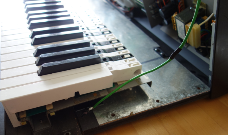
You either need to flip the unit on its back, balance it upright on the back edge as you remove the screws. Either way, it’s awkward and risky. (It was at this point I realized the standing desk was probably a bad idea.) Restoring it to the normal position, the lid then swings up for easy access.
If I recall correctly, there’s an earthing wire that will possibly prevent the lid opening to a useful working angle. In my unit, I’ve lengthened the wire so that I don’t have to unscrew one of the lugs, but your unit may be different. Use caution.
Now we’re ready for the next step.
Removing the keybed
If you’re only interested in removing the black keys, you don’t need to remove the keybed from the chassis: Black keys slide out towards the back; White keys towards the front (where there is no room in the assembled unit.
Removing the keybed requires:
Disconnecting the cables;
Unscrewing the keybed from the base.
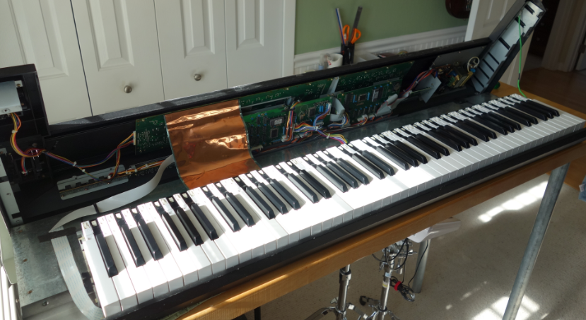
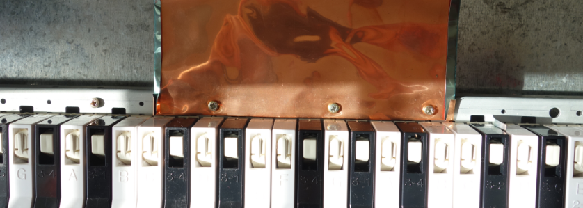
Disconnect the copper shield
It’s attached to the keybed by three screws:
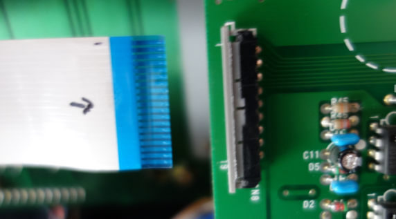
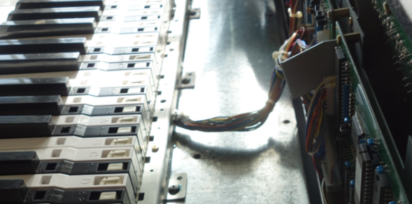
Unplug the “key pressure” ribbon cable
It is easy to unplug the cable from the CN8 connector on the MAIN-A board: Mark the ribbon with a sharpie so you can re-connect it correctly later (optional). The receptacle clamps down on the ribbon edge and easily releases the cable if you tug gently on the grey section of the connector to open it:
Once open, the cable slides free
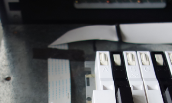
The ribbon cable is retained by a flexible clamp, and in my unit, a strip of tape holding it to the base plate.
Cable retainers also need to be released
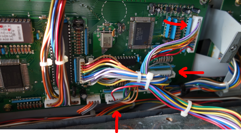
Unplug the PCB connectors RA1, RA2, RA3
In my unit I had to snip a cable tie that was grouping all the wires together. Now that I write this, I realize that I forgot to replace it. Oh well, no big deal. RA1, RA2, and RA3 are marked on the PCB.
Connectors RA1, RA2, and RA3
If necessary, you can use a small screwdriver to loosen the connectors. They are keyed, you can only insert them one way.
Unscrewing the keybed from the chassis
There are 12 screws to remove: 6 from the inside back edge, and 6 from the underside at the front of the chassis. These are indicated as “II” and “III” in Fig.1 above.
Three of six to remove from inside
Now we can lift the keybed out of the chassis and place it on a clean padded work surface. Take care to protect the ribbon cable – it is still attached, and is fragile.
Now would be a good time to take a vacuum cleaner to the interior of the chassis. I don’t know about you, but my unit was pretty filthy inside under the keys.
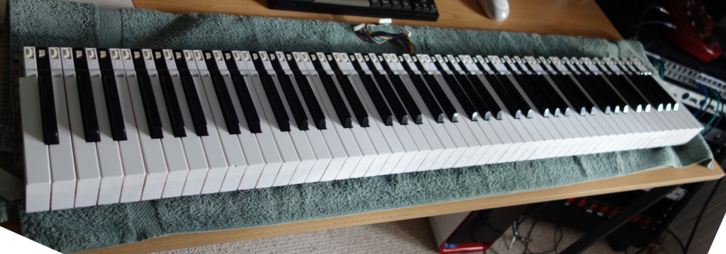
Reviewing the keybed
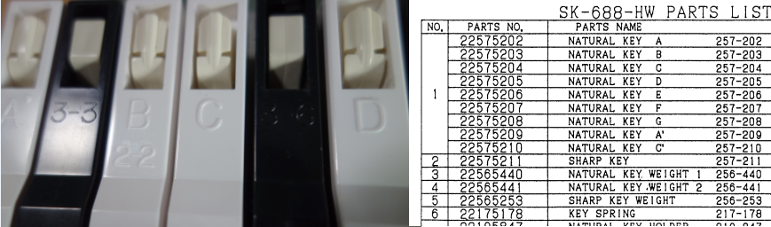
Replacing the felt “lowers” means that I’m going to have to remove all the keys. I took some time to review the keys. Each key has an identifier embossed near the hinge. For White keys, its the Scale note (except for one B key which also says “2-2”, and the first and last keys which are A’ and C’ respectively). The Black keys seem to be a random 3-1, 3-2, 3-3, etc, up to 3-6. I can’t see a correspondence between scale position and number.
The parts list on page 4 of the service manual does not give any hints about these codes. I don’t think it is significant, apart from the obvious non-standard keys at the top and bottom ends of the keybed. However, as I put the removed keys aside, I made sure to line them up in order so that I could replace them exactly the same way. I recommend that you do the same.
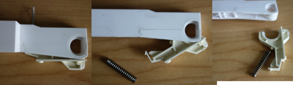
Removing the keys
Each key consists of a key Holder that is attached to the base, and the Key itself which hinges on the holder, and depresses when you play a note. Removing a key from the base involves reaching through a hole in the Key and lifting a catch on the Holder to allow the holder to be slid out of the base. White keys slide towards the front, whilst Black keys slide out towards the back.
Page 6 of the Service Manual attempts to describe the process clearly, but in all copies I’ve found on the Internet, there appears to be some text missing.
Essentially, the process is:
Depress the Key
Insert the key removal lever and rock it towards you so that the tooth engages the Key Holder latch (it is exposed while the Key is depressed)
Lift the key removal lever slightly to ensure the lock button at the base of the Key Holder is raised out of the hole in the base
For White keys, push at the back to slide the Key Holder towards the front.
For Black keys, push on the front of the key to slide the Key Holder towards the back of the base.
The Key + Key Holder should then lift away from the base.
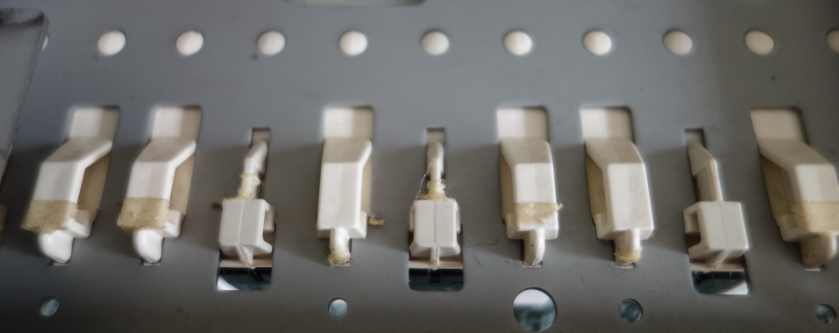
Having a look at base with keys removed make this more understandable:
The Key Holders fit into the notches in the base plate. Black keys lock in from the back; White keys lock in from the front. You can see the round hole that the lock button fits into… here’s a view from the back:
Another view, from below
The key removal tool is for lifting that button out of the hole, via the tooth latch on the key holder.
There’s nothing like trying it out in practice.
One thing you may encounter is that there is a whole lot of double-sided sticky tape all over the base plate, and the key holders are very firmly held in place. It took some force to dislodge them. Sliding them out while holding the key removal lever in place was tricky.
When I started removing the keys, the holder and key would separate and the spring would fall out. Not a big deal to re-assemble, but it’s best to avoid it if possible. Knowing the mechanics ahead of time might help with this.
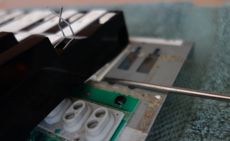
With the paper-clip version of the Key Removal Tool, I had difficulty lifting the Key Holder lock. Seeing as I was starting from one end and removing all keys, I could use a small screwdriver from the open side to assist in the release:
You can see how ineffectual the paper-clip is in obtaining leverage
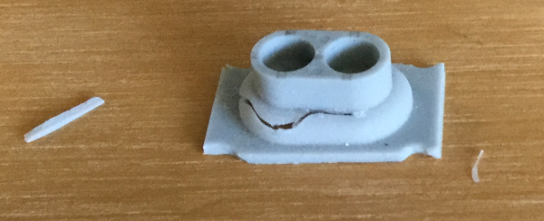
However, using a screwdriver has risks. After two decades or so, those rubber domes are fragile. USE CAUTION! DO NOT LET THIS HAPPEN:
Cue Hitchcock Psycho strings in D
That’s the D4 key. So long as I don’t poke it, I can’t see the break in the rubber, and I had to hope that the switch was still functional. If not, I’d find out later.
Things were much easier when I gave up on the paperclip and manufactured my own key removal tool.
Some well-spent time with a vice, hammer, and flat bastard file later…
The thickness of the “blade” at the business end isn’t specified, but the thinner and more polished it is, the easier it will be able to latch on to the plastic catch inside the key.
Imagine you needed a knife for something, couldn’t find one cause all you found was 10 000 spoons…. it could happen!!! And therefore you couldn’t do whatever it was you needed the knife for, and then the next day it turned out that a spoon would have done.
Ed Byrne
With all the keys removed I debated trying to remove all the old excess double-sided tape, and decided that, maybe it was there for a reason, and left it.
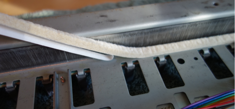
Replacing the key felt
This part was easy. It’s also the part where I realized that it was a good thing I ordered two units of key felt, because it took one unit just for the White keys alone.
This new felt feels a little thicker than the old strip.
With the felt replaced, we can re-insert the keys. No special tool is required for this.
Be warned that the thicker layer of felt on the underside means that there is slightly less room available when maneuvering the key into place. I took my time and tried to protect the rubber domes as much as possible from accidental shear forces as the key holder slid into the slot and locked in place.
Problem #1
A side goal of this whole adventure was to take a close look at C#5 which has always been a little “sticky”. It never quite bounced back as quickly as it should, and very occasionally stuck in the depressed state. Sure enough, when I re-inserted it into the base, the same behavior – actually worse – was observed.
Process of diagnosis:
I tried swapping the grey plastic guide with one from a known “good” black key position, and observed the same problem.
I swapped the key itself with a “good” one and, again, observed the sticky bounce-back.
I removed the guide completely, and the key bounced back freely – nice – but with a lot of unacceptable “slop” from side to side.
I decided that either the guide post itself must be bent (not visually apparent), or the key holder slot slightly out of alignment (I find that hard to believe).
The solution I settled on involved removing the grey plastic guide and shaving the sides down a fraction, then re-lubing with a slight amount of grease. Fortunately this was sufficient and the re-installed C#5 key now returned to the upright position snappily. Success!
Reconnecting and Testing
With the keys restored to position, I lifted the keybed back into the chassis and screwed it in place; Reconnected the plugs and ribbon cable, and copper shield.
Anticipate the worst
You’re going to need to connect the mains power and a MIDI out cable;
You’re going to need to test every key on the board, with a sound source that is responsive to velocity;
You’re going to find out that something isn’t working;
You’re going to have to go back in to the keybed and try to fix it.
Alternatively, just screw the lid back on and heft the A-80 back into your normal position in the studio, and hope for the best. I chose this second option. I recommend that you suppress your optimism, and assume the worst. Get the A-80 into a place where you can test the MIDI output and still investigate keybed issues.
First good news: I found that the D4 functioned normally. That damaged rubber dome switch isn’t affecting the key response. Phew!
Problem # 2
However, G#4 seemed WAY too sensitive, belting out a velocity close to 127 no matter how gently I pressed the key. Ugh.
There’s nothing for it, but to open the lid and remove that key and examine the rubber dome switch.
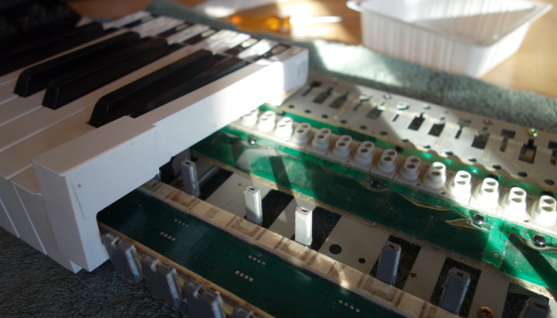
Pro Tip: If you are diagnosing a Black key, then you do not need to unscrew and move the keybed from the chassis.
I unscrewed those 12 screws, and moved the keybed back towards the rear of the chassis to get clearance at the front; then raised it up an inch or so on wooden blocks so as to give all keys a clear travel path when depressed.
Then I realized that I didn’t need to do any of that, because I was only interested in one Black key. And they pop out from the back of the keybed, not the front.
After removing the key, I pressed the rubber dome with my finger. It seems that it was possible to emit notes with a wide range of velocity values. The dome switch did not appear to be at fault, but it is hard to judge sensitivity with a finger.
I tried carefully re-installing the key, to see if it was just debris or dust, but it didn’t make a difference. I also tried swapping over to a different Black key to see if it helped. It made a slight difference but still not acceptable – it was just too hard to get softer notes and compromising playing technique for that one key is not really feasible.
Testing in place with Pianoteq 7
I examined the black plastic key at the point where it pushes down on the rubber dome switch. You can see from the schematic further back in this post (Fig.3) how the key, when depressed, impacts the dome switch at an angle. This causes the switch to close two sets of contacts in quick succession, and the time difference between the two circuits closing is translated to “key velocity”. It’s pretty accurate, when working correctly.
For whatever reason, this specific rubber dome was closing the two switches almost instantly, regardless of actual key depression rate.
In desperation, I took a file to the key and very carefully induced an angle in the flat underside of the key, such as to accentuate the timing difference in how the key impacted the two parts of the rubber dome. I don’t have a photo of this unfortunately (I wish I did, but I’m not opening up the A-80 again to get one).
Installing the key and re-testing demonstrated that my hack had made a difference. The velocity response on G#4 was now closer to that of the other keys. It’s not perfect but it’s very usable. It is still a “sensitive” key. I can live with it.
Conclusions
On the whole, the operation was a success. I think I dodged a bullet with the torn rubber dome on D4, and taking a flat bastard file to a key component to fix the problem on G#4 isn’t ideal by any means, but it seems to have worked. C#5 is no longer sticky.
The keybed is about 50% quieter and feels smoother. I did not replaced the “down” felt because it is aligned with the polyphonic after pressure sensors and I wanted to avoid messing with those. But much of the noise was due to “bounce-back”, and that has been reduced a lot.
The Black keys seem unaffected by the new felt with respect to key travel, but the White keys have a reduced “throw”, and feel…. tighter. This must be because their resting position is slightly closer from where it used to be, due to the new felt strip. I expect the new felt will compress a little further as time goes by, but the difference isn’t bad. It feels like an improvement. So, yay.
I hope you’ve enjoyed this tale from the workshop, and maybe even found some information that helps you out in your projects. Drop me a line if you have questions.
Melodic progressive rock songs and instrumental interludes, a touch of 70’s influence but a product of the dystopian Now.
“Very smooth, hi-tech sounding delivery…” – Chris Jemmett, alt.music.yes
“This guy is awesome.” – Dazed, on the Carvin Forum.
“..on a rare occasion you just have to conclude that the prog world should be feasting upon the birth of a new and promising act. That’s exactly the case with this [first] album.”
– Theo Verstrael, DPRP.net
“I find this new album attractive, [..] slightly less appealing than the 2014 debut. But as that is often the case with great artists, let it not distract you from trying this fine album. Especially those that are interested in bands that play varied, cleverly made, well played and sung [..], this might just be your cup of tea.”
– Theo Verstrael, DPRP.net

Recent Comments