I can’t remember exactly when I purchased my Korg EX-8000, but based on archival recordings, it must have been around 1991. It made the trip across the Pacific from New Zealand back in 1999, and it has been in storage for roughly the last decade, along with other items of equipment that I don’t have room for in my tiny studio.
At this point, I’ve decided that someone else should be enjoying this 8-voice DCO synthesizer with analog resonant filters of goodness, and I should find another home for it.
Before I can do that, I have to make sure everything is still in working order.
In the case of synthesizer keyboards and modules, providing the item has been stored correctly in a cool and dry location (which of course is the case here), then the most likely problem will be that the patch and configuration memory storage has been lost due to the internal battery running out of charge.
Indeed, this was exactly the case. Upon plugging the EX-8000 into my Philmore ST-1000 heavy duty step-up power transformer, 220V output, I discover that no sound can be produced from pressing the keys on a connected MIDI keyboard, but that pushing the “A4” button on the front panel will produce a “tick”. Reviewing the parameter values, clearly we have a corrupted memory because some of the values don’t make sense, although spinning the value editor dial will soon bring them back into line.
With some tweaking I can turn the “click” into a siren or “bloop”. Progress! All 8 oscillators appear to be in good shape, providing I can restore the memory.
Alas, upon bouncing the power on the unit, all my parameter edits have been lost. The backup battery is almost certainly the culprit. Time to open her up!
Replacing the battery
1. Remove the rack-mount ears
2. Remove 6 screws holding the cover in place (2 each side, and at the back)
Apart from the power supply and the I/O boards, the two main boards of the synth are in a sandwich configuration. You can remove 3 screws and swing them up on a kind of plastic hinge:
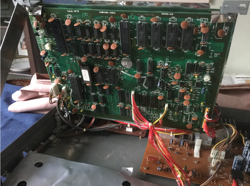
You need to do this to access the battery, plum in the middle of the underside. I use a ruler to carefully prop the boards upright.
I could see some green crusty stuff around the battery which isn’t a good sign.
Okay, now the bad news here is that the CR-2032 battery is actually soldered directly into the PCB via a little bracket. You can’t just pop the battery out and replace it. The only sane option here is to remove the lower PCB from the chassis and replace the battery+bracket with a true low-profile socket.
Fortunately, this is not too difficult. I recommend taking a lot of pictures of the cables and connectors to make sure you know how they are laid out and connected.
3. Unplug all cables from the board
4. Unscrew the four screws at each corner holding the PCB to the metal brackets
WARNING: The two orange pin arrays on the bottom right are soldered directly in, they are not plugs!
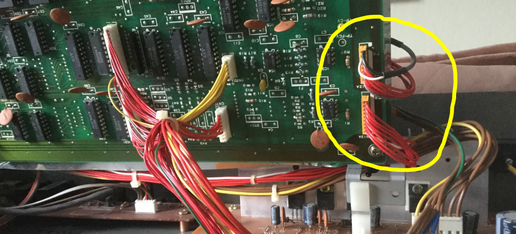
Instead, you need to trace them to the other end, around the other side of the sandwich, and unplug the other end from the “top” board.
Then you should be able to remove the board from the unit:
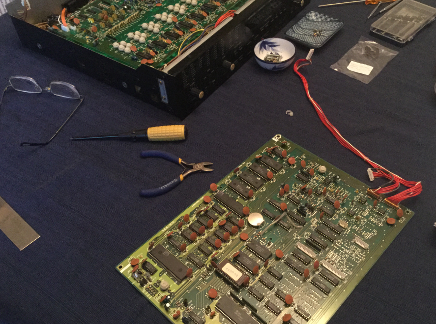
Replacing the corroded battery and bracket is very easy if you’re handy with a soldering iron and a solder-sucker. The socket I used didn’t quite line up with the vacated holes in the PCB, but a little wire lead and some silicone caulk (and some heat-shrink) yielded a nice result:
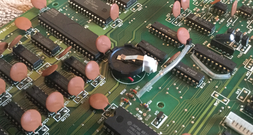
After a new CR-2032 battery is inserted into the socket, and the board mounted safely back in the case with the leads re-attached (refer to those pictures you took!), and a quick test proves that any parameter change I make is retained during a power cycle. Hooray!
Restoring the default patches
Fortunately, other folks have done the hard work on finding the patches, and restoring them turns out to be more-or-less straightforward.
There’s two ways to restore patches:
- Play a .WAV file into the tape FROM port on the unit
- Use a SYSEX loader to load the patches in via MIDI
Tons of good information here:
- https://www.muffwiggler.com/forum/viewtopic.php?p=606314
- http://www.dw8000.com/downloads.html
- https://www.pallium.com/bryan/dw8000.php
- https://www.pallium.com/bryan/dwpatches.php
After some initial trouble of getting levels set correctly, I succeeded using the .WAV file following this process:
- Email the .wav file to myself as an attachment
- Open the email on my iPhone
- open the attachment
- connect iPhone to the TAPE FROM socket using a normal stereo 3.5 mm jack lead
- set my iPhone playback (headphone) volume to MAX
- switch the EX8000 FROM TAPE level switch to LOW
- switch the EX8000 TAPE switch to ENABLE
- press LOAD
- tap the iPhone to start playback of the .WAV file
After some flashing, the bank numeric indicator cycled through the banks, and the LED display said GOOD. Success! Those patches sound great.
Switching power supply from 230V (New Zealand) to 120V (US)
The final step in getting the Korg EX-8000 ready to leave the studio is to convert it to use a 120V mains supply voltage. When I started this process, I figured I’d need to replace the mains power transformer but, no, it’s way easier than that! The transformer already handles multiple voltages. From the service manual:
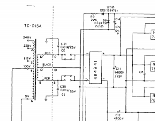
Yeah, that ‘former has multiple taps on the primary side. In real-life:
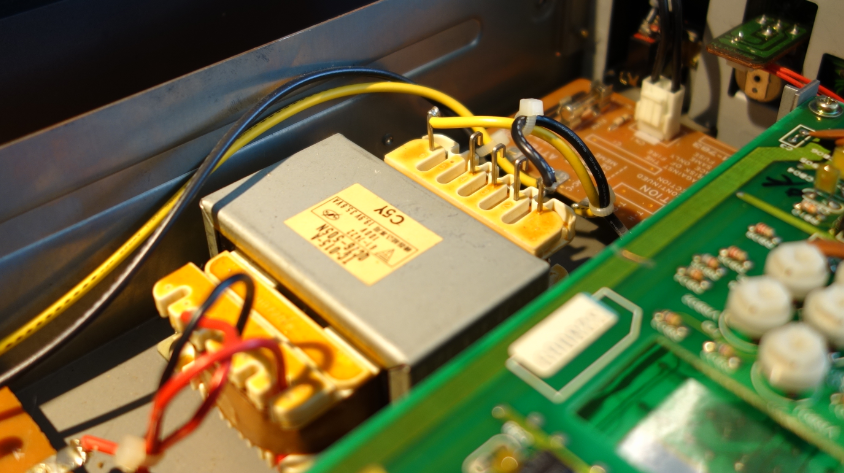
Although you can’t see it in this image, the terminals are actually labelled with the numerical identifiers. On my unit, the mains leads (black+yellow) deliver voltage to terminals 1 and 6. According to the schematic, that matches a 240V supply, which is best match for the NZ mains voltage of 230 V.
The schematic offers both 117V and 100V terminals (3 and 4) and suggests that terminal 4 should be used by default – It would be nice to think that the Service Manual is assuming a US standard mains supply, but that’s probably not a good assumption. The Service Manual says “Tokyo/Japan” on the front page, and Mains Voltage in Japan is 100V.
In the US, it’s 120V, although it used to be 117V. Terminal 3 seems like a better choice.
The PSU board has three connectors – CN2A, CN3A and CN4A – which I disconnected to protect the rest of the unit from any screw-ups in voltage changes.
Then I tested the voltages coming out of the transformer and measured 10 VAC from Black to each of the Red wires.
On CN3A I measured 5 and 10 VDC from the center pin to each of the outer pins. That’s our baseline, our known “good” values using the 220V mains supply.
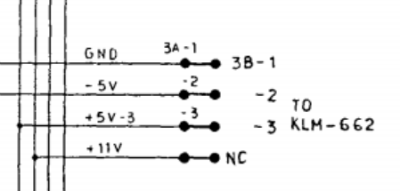
The CN3A lead indeed does go to board KLM-662, and according to the schematic, should be supplying 0, –5, and +5 V on pins 1, 2, and 3. (See above).
So, that matches my observations (-5 : 0 is +5; and –5 : +5 is +10).
At this point I performed some soldering: Moving the black lead from pin 1 to pin 3 on the primary side of the transformer; and also replacing the mains socket from the proprietary 2-pin KS-17 to a more common IEC standard appliance socket.
See: http://www.dw8000.com/projects.html
Once that is done, it was time to plug into the regular US mains and re-test those voltage readings. Excellent, all looked the same as before. Could it be this easy?
Apparently, yes. I’ll run it for a while on 120V in my studio, and see if anything blows up. Either I’ll fall back in love with this sound module, or I’ll see about putting it on CraigsList or something.
Thanks for this helpful posting. I am following your instructions for replacing a defunct battery. I note some other board mod in your picture near the battery. Mine doesn’t have that. Do you know if that was a later board rev, or some kind of user tweak or repair?
Hi Weldon, thanks for writing. Are you referring to the wires/resisters encased in the translucent tubes? I assume so. Yes, they were there when I opened it up.
I purchased the unit second-hand so I can’t swear it wasn’t a user-mod, although my guess it is a factory mod. Unfortunately I don’t have easy access to the EX-8000 currently so I can’t check the dates on the back panel or the board rev numbers.